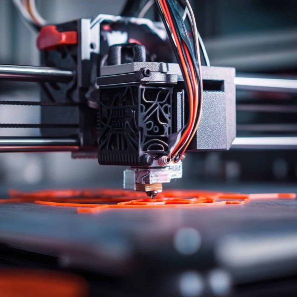
Prototyping & Product Development
3D printing is widely used to quickly create prototypes for testing form, fit, and function. It allows teams to iterate designs rapidly without expensive tooling.
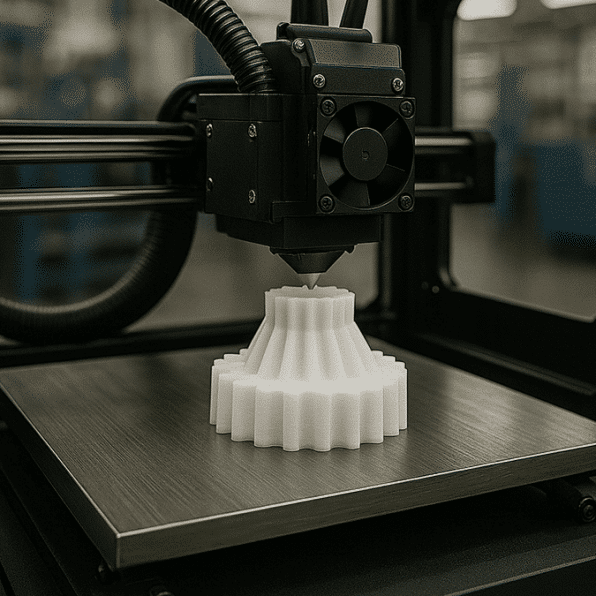
Custom Manufacturing
The technology enables production of highly customized or personalized parts, such as consumer products or specialty components. Each item can be modified digitally without impacting production efficiency.
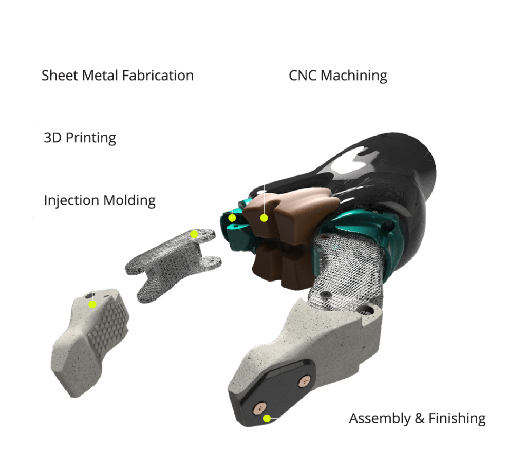
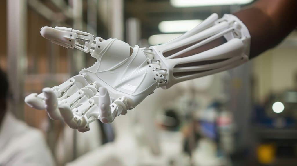
Healthcare & Medical Devices
3D printing is used for patient-specific implants, prosthetics, surgical guides, and anatomical models. This improves fit, surgical accuracy, and patient outcomes.
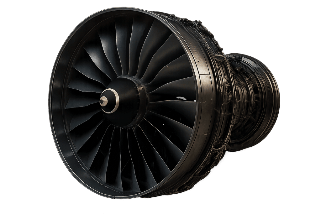
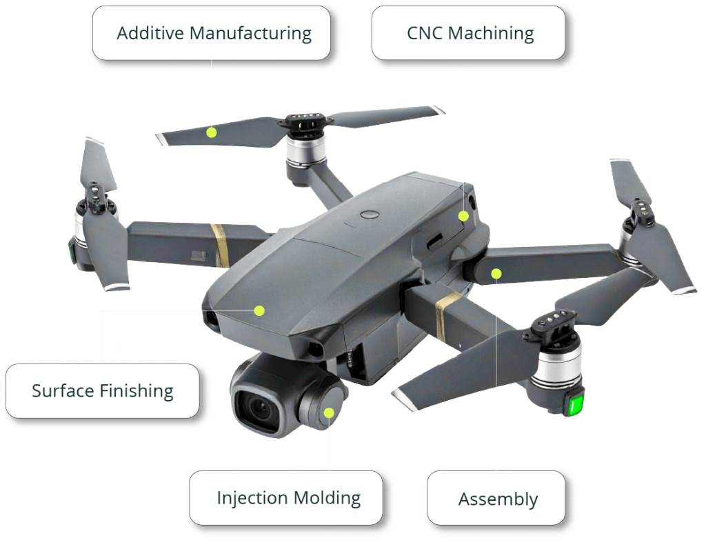
Aerospace & Automotive
Manufacturers use 3D printing to produce lightweight, complex parts and tooling. It helps reduce part count, improve performance, and accelerate design validation.
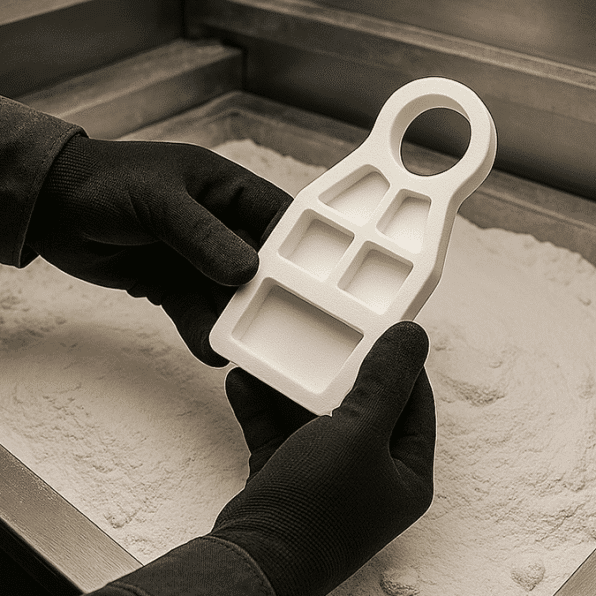
Tooling, Jigs & Fixtures
Custom tools, jigs, and fixtures can be printed quickly to support manufacturing and assembly operations. This reduces lead times and lowers costs compared to traditional toolmaking.
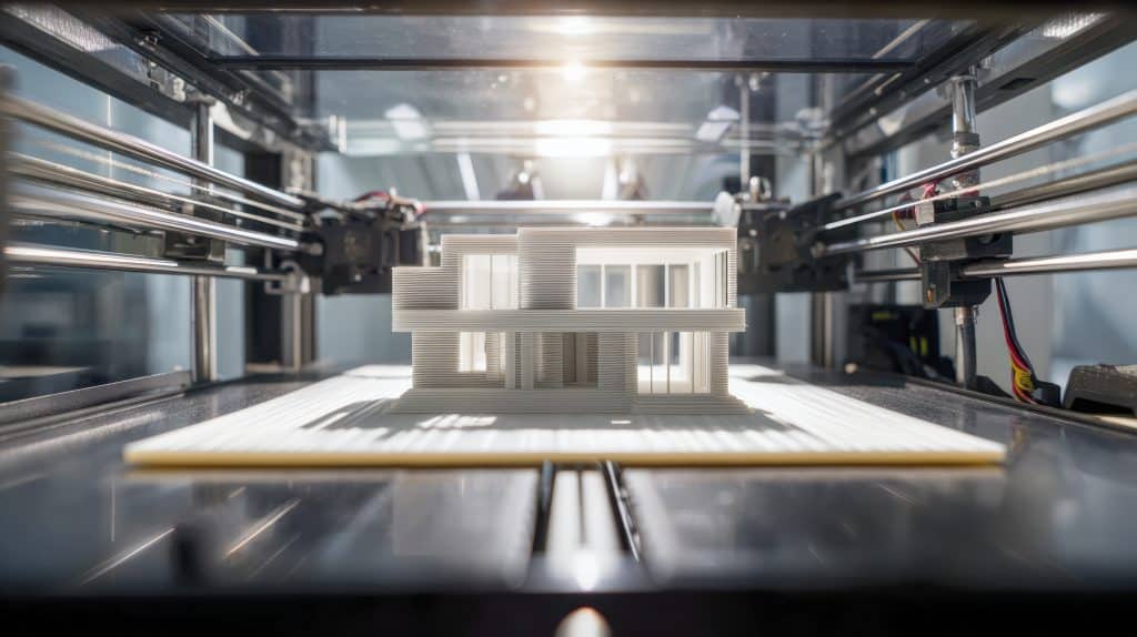
Architecture, Construction & Design
3D printing is used to create detailed architectural models, construction components, and design prototypes. It allows architects and builders to visualize concepts, test structures, and explore innovative building methods more efficiently.