Multi Jet Fusion 3D Printing
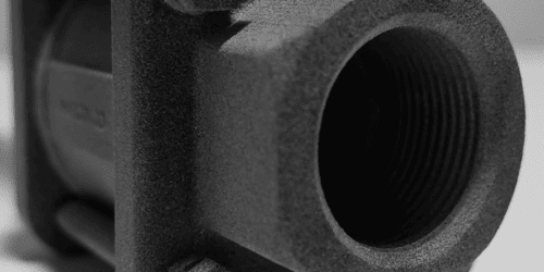
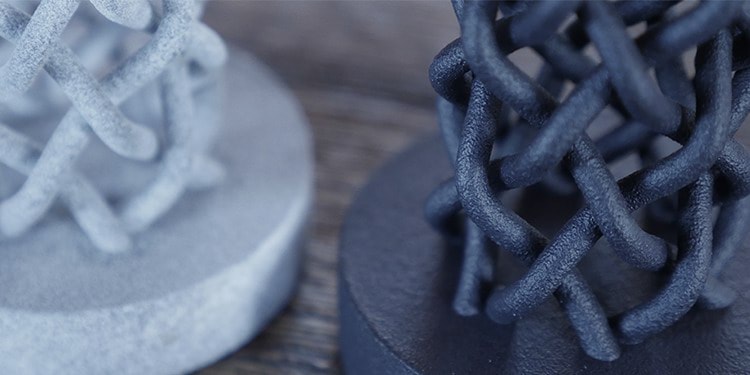
Multi Jet Fusion (MJF) is quickly becoming a popular choice for 3D printing prototypes and production parts. Ideal uses for MJF are enclosures, electronics housings, complex ducts, lattice structures and functional assemblies. The technology is capable of 3D printing parts with high detail, as well as suitable for applications that require durability (e.g., snap fits). It is common for designers and engineers to choose this material for short production runs. Offering this technology adds to Fathom’s already comprehensive 3D printing and additive manufacturing services.
How does MJF 3D Printing Work?
MJF technology builds parts by laying down a thin layer of powder on a print bed over and over. The inkjet array in the print carriage sweeps over the print bed, jetting two agents downward—a fusing agent, printed where the powder will fuse together and a detailing agent that is used to reduce fusing at the part boundary to achieve greater detail.
Applications of Multi Jet Fusion //
Parts with smooth surfaces and complex, intricate features can be achieved using Multi Jet Fusion. Other applications include //
- Functional Prototypes
- Rapid Prototyping
- End-Use Parts
- Housings
- Complex & Organic Geometries
- Parts With Fine Features
- Projects Requiring Consistent Isotropic Mechanical Characteristics
- Projects Requiring a Smooth Surface
- Low-Volume Production
MJF Materials //
| STANDARD MJF MATERIAL |
LEAD TIME | OPTIMAL QUANTITY |
MAXIMUM DIMENSIONS | SUGGESTED MINIMUM WALL THICKNESS |
FINISH & APPEARANCE |
ADVANTAGES & CONSIDERATIONS |
|---|---|---|---|---|---|---|
| Nylon 12 (Gray or Dyed Black) | 2+ Days | Prototypes, Low-Volume, Short-Run Production | 274mm x 370mm x 360mm | 1mm |
|
|
Nylon 12 is a commonly used thermoplastic that is strong enough for functional prototyping and production parts, small to medium in size. Nylon 12 is ideal for complex assemblies, housings, enclosures and watertight applications. Achieve smooth surfaces and fine details with this durable material. It provides excellent chemical resistance to oils, greases, aliphatic hydrocarbons and alkalies. Parts produced are a non-uniform light gray, but can be dyed a darker color for a uniform appearance.
AMT PostPro3D Finishing / /
AMT’s PostPro3D technology is a smart and automated post processing solution for smoothing MJF 3D printed parts. PostPro3D achieves a high quality surface finish that matches injection molding techniques using 3D printing processes. This enabling technology reduces lead-time, cost of manufacture, operational and maintenance costs providing the ‘missing piece’ in the digital manufacturing chain. The PostPro3D machine makes 3D part surface finishing speed and cost competitive for high volume production.
MJF Parts & Images //


Advantages & Disadvantages of MJF 3D Printing //
Before you select MJF for your project, you will want to become familiar with the benefits and limitations.
Advantages Include //
- Smooth Surface Finish // There are no markings left from removing supports because no support material is needed. The result is a smoother surface with the possibility for crisp edges.
- Cost-Effective // Multi Jet Fusion can be cheaper than other additive manufacturing processes.
- Faster Turnaround // Multi Jet Fusion is a fast process because during the printing process the entire layer is heated. This is different from an SLS process where a laser traces the area.
- Eco-Friendly // MJF printers reuse any leftover excess material resulting in less waste.
Disadvantages Include //
- Limited Material Choices
Multi Jet Fusion vs. Selective Laser Sintering //
During Selective Laser Sintering (SLS), powdered material is laid down in a thin layer on the build platform. Each cross-section is scanned by a CO2 laser which sinters the material. The platform shifts down one layer and repeats until the part has been made. The part is then removed from the platform after the bin has cooled.
While both Multi Jet Fusion (MJF) and Selective Laser Sintering (SLS) use thermoplastic polymer powder material, there are key differences. The primary difference is the source of heat used during the process. SLS uses lasers to heat each cross-section. MJF uses a fusing agent (ink) distributed onto the powder while an infrared light passes over the platform and fuses the areas that have been inked. Additionally, fusing during MJF happens in a line while SLS fuses each cross-section point by point. While the excess unused material in both technologies can be salvaged and recycled, a greater amount is retrieved by Multi Jet Fusion. Another difference is color. SLS parts are printed in white and then dyed. They may also be gray. MJF parts are printed in light gray and can be dyed black. Both technologies end up with a grainy finish, but can achieve a high standard of quality during post-processing.
Multi Jet Fusion Questions Answered //
Q // Who Invented Multi Jet Fusion?
A // Multi Jet Fusion was developed by Hewlett-Packard (HP).
Q // What Geometries Can Be Achieved With Multi Jet Fusion?
A // Parts that require internal cavities and complex geometries can be made using Multi Jet Fusion.
Q // What Color Options Are Available & What Is The Surface Finish Like?
A // Parts produced are a non-uniform light gray and can be dyed in dark colors to achieve a uniform appearance (choosing to dye parts will extend lead-time). These parts will feel grainy, similar to other power-based systems such as SLS, but can be further post-processed if desired.
Q // What Are Part Size Limitations?
A // The bounding box of the 3D printing system is 284mm x 380mm x 380mm (11.18″ x 14.96″ x 14.96″). Parts beyond this size can be split and adhered together during post-processing.
Q // What Is The Standard Accuracy, Layer Height & Minimum Feature Or All Size?
A // Expect an accuracy of +/-0.3mm up to 100mm or +/-0.003 mm per mm beyond 100mm. The layer height is 80 microns. Fathom recommends a wall thickness minimum of 1mm.
Q // What Is The Minimum Gap/Hole Size? Can You Tap Threads? What Is The Minimum Thread Size?
A // Minimum gap is typically 0.5mm between features. For tapping threads, Fathom suggests using threaded inserts for anything under ¼-20 threads.


