Injection Molded Plastic Part Shrinkage
 Plastic shrinkage or mold shrinkage is an important consideration when designing any part for injection molding. The two terms may be used interchangeably but it is important to note that mold shrinkage refers to the dimensional change of the injection molded object as it cools, while plastic shrinkage can be used to refer to the characteristics of a specific plastic. Designers must take into account the shrinkage and contraction rate of the injected material and how that will affect the shape of the part.
Mold shrinkage is the dimensional change that occurs in a molded part as it cools after injection. Mold shrinkage is usually stated as a percentage. Most of the shrinkage occurs while the part is still within the molding tool during the cooling stage, but a small amount of plastic shrinkage may occur after ejection, as the part continues to cool. This is especially true for plastic materials like Delrin or Polyoxymethylene.
The majority of excess heat has been already dissipated and the most of shrinkage has occurred before the part is ejected from the mold. The part may continue to shrink slightly for several hours or even days until the temperature and moisture content stabilize to match the surrounding environment. Any dimensional inspection should wait at least a day after part ejection to maintain consistency and suitable part stabilization
How Do You Calculate Mold Shrinkage?
Plastic injection molded part shrinkage units are expressed as thousandths of an inch per linear inch (0.00X /in/in). Typical shrink rates vary between 0.001/in/in and .020/in/in – depending on material, wall thickness, cooling rates and other variables. The average rate of shrinkage is around 0.006/in/in.
How Is Shrinkage Value Calculated?
Mold shrinkage calculations can also be expressed as a percentage. The percentage can be found using the mold cavity dimensions and final part dimensions.
S = Shrinkage Rate
Y = Cavity Dimensions
Z = Part Dimensions 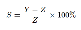
If the Cavity Dimension is 1.7 in. and the Part Dimension is 1.5 in., the part shrinkage can be calculated thusly: 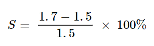 S = 0.0013 in. or 0.13%
Model vs. Mold — Compensating for Shrinkage in Both
When considering mold shrinkage calculations, the tooling engineer simply scales the mold tooling by 1.00X. In pre-CAD days, the engineer would compensate for mold shrinkage by enlarging the part. This is done by multiplying every number on the drawing by 1.00X. At ICOMold, the mold shrinkage calculation takes place during the mold building stage, so the stabilized part dimensions should align with the CAD model specs and part prints. In other words, ICOMold compensates for plastic shrinkage in the mold design so that the part specs match the model.
Plastic injection molding shrinkage will also vary with wall thickness. The material supplier will usually provide a material data sheet that specifies a shrinking range for the material (e.g. 0.005-0.007/in/in for a 0.100-inch wall thickness). In turn, if the wall is 0.100 in. during validation and inspection, the shrink average along those walls is expected to be 0.006 in. It is critical to factor in the shrinkage rate at the tooling design stage for any parts with tight tolerances. This will ensure that the final parts meet the model specifications.
Fine Tuning Shrinkage Compensation
The molder can fine-tune the shrinkage of the parts by adjusting the density of the material. This can be done by manipulating how hard the cavity is packed or by extending the cooling period in the mold. ICOMold will always recommend performing test shots prior to injecting parts that are large, parts that have tight tolerances, or using a new or unusual material.
Many injection molders will have a large supply of obsolete molds. Asking the company to do a test shot on an obsolete mold of similar size to your project is an easy way to see plastic shrinkage first hand. Ask for a mold in a similar in size, shape, and wall thickness to your part design. The molder will shoot the desired resin into the mold for a small fee. These parts can be used to calculate a precise plastic shrinkage for the chosen material. While this step may take extra time and add a little extra cost, it can be very beneficial by saving time and money later on if the mold needs to be reworked or even scrapped due to parts being out of tolerance. ICOMold can perform this service for a small fee’ following a tooling PO.
Asymmetrical Shrinkage
Different plastic materials will behave differently due the complex chemical composition of polymers. It is critical to review the material data sheet prior tooling development. Another layer of complexity is added for materials with asymmetrical shrinkage characteristics. These are plastics that have different shrinkage rates depending on the part orientation.
Polymers filled with long glass fibers will shrink more in the cross (transverse) direction than the longitudinal (flow) direction. This poses an interesting dilemma for the mold designer. The material supplier documentation will state there is a different shrink rate along the X-axis than there is along the Y-axis. This is not much of a problem for long straight parts like candy sticks or rulers, but can be challenging for parts with complex geometries.
If the part is complex, and includes features like holes or flow fronts that meet at different angles, it can be impossible to calculate and model the plastic shrinkage with complete accuracy. The time and cost to model the result would be an expensive and unnecessary study, even if it could be performed to a desired level of confidence and reliability.
This can even include simple geometries like round holes. The round hole could become elliptical due to the molten plastic flow and the subsequent shrinkage relative to the direction of the fibers in the material.
An approximation of the mold shrinkage is applied to the entire part by averaging the shrinkage between longitudinal- and cross-shrinkage. This will enable the molder to make a good first-round approximation. The customer will then be required to sign off on the approach due to the possible variability in the production run. Critical features are then altered or added after first shots, based on the analysis of the material flow and subsequent shrinkage. It is best to avoid resins with asymmetrical plastic shrinkage if the design calls for tight tolerances.
Plastic Shrinkage Calculator
Plastic shrinkage calculators and mold shrinkage calculators do exist, however, due to the many variables in the injection molding process, it is better to calculate mold shrinkage with the help of the experts at ICOMold. The experts at ICOMold will be able to identify any issues with the design and help the designers compensate for shrinkage and the variables that drive shrinkage.
For more information on plastic shrinkage and mold shrinkage, contact the experts at ICOMold by Fathom. The experts at ICOMold have decades of experience to help customers take their parts from design to production.